Upscaling your 3D grid
The upscaling process available on the Upscaling & Layers form described below allows you to create an upscaled simulation grid based on an existing grid. The latter is created using the 3D Gridding workflow or can be imported from another application, for example a Petrel/ECLIPSE™ pillar grid. The upscaling process can also be confined to a specific part of the grid, such as a particular reservoir, resulting in an upscaled grid that only represents the chosen region of the original grid.
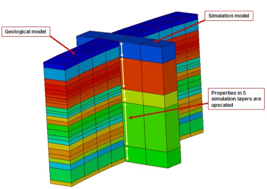
Grid upscaling
Grids can be scaled in both the lateral and vertical directions. Lateral scaling can be achieved by modifying the number of steps, which groups cells together, while vertical upscaling is dependent upon the settings in the Model Definition View, which can be opened from the form. Imported ECLIPSE™/IJK based grids can also be scaled laterally, however, unexpected results near faults may be encountered; it is suggested that you verify the model after the upscaling process has finished.
Property upscaling
Basic grid properties can be upscaled during the 3D grid upscaling process. For every grid property available on the 3D Grid form, a separate upscaling method can be specified. You can also use the property mapping functionality in the Property Mapping Tool and in the model > Facies or model > Rock Properties sub-strips where you can map additional properties from the source grid to the upscaled grid without having to re-generate the upscaled grid.
To upscale the grid
- Open the Upscaling & Layers form (model > 3D Grid > Grid from Grid).
- Select the source grid that you want to upscale from the drop-down box. The lateral and vertical dimensions of the selected grid are displayed in the text boxes directly below the drop-down box and can be used for reference/information.
- Type in a name for the upscaled grid that will be produced as a result of the upscaling process.
-
Specify the lateral upscaling dimensions for the simulation grid using the 'Start', 'End', and 'Step' controls. At the bottom of the form the dimensions of the upscaled grid are displayed. For each change you make in the 'Start', 'End', and 'Step' controls you will see it reflected at the bottom of the form. See the table below for details on each control.
Start / End Identify the lateral area on the grid that is to be used in the upscaling process. This is done by entering the relative coordinates of the starting and ending grid cells at each corner of the source grid. For example, if the source grid is a 20x20 grid, the first corner cell would be 1,1 and the opposite corner cell would be 20,20.
Step Lateral upscaling can also be done using step size. Based on the specified step size, the lateral grid stack will be merged together. The larger the number of steps defined, the coarser the final grid will be.
-
The Model Definition view is used to define the vertical upscaling. Click the Show model definition view button to open the view and specify the layers using the remaining buttons, which can be used to further define the model layers. Each of the buttons is described in the table below.
Show model definition view Show the Model Definition view of the source grid. The buttons described in this table will become active when the Model Definition view is open.
Impenetrable Marks the selected layer(s) as impenetrable. Visually, this changes the layer border(s) to a gray bar marked with an X.
Penetrable Marks the selected layer(s) as penetrable. Visually, this changes the layer border(s) to a green color.
Group Groups the selected layer(s) and overlays a group number.
Ungroup Ungroups the layers in the selected group and removes the group number.
1-on-1 grouping Convenience function to define every model layer without any child model layers as a single group.
Reset grouping Function to ungroup (reset) all grouped model layers in one group.
Keep each (internal) layer Function that overrules all grouping and penetrable settings and defines all k-layers on the deepest level as a single group. This takes into account all internal layers too. As a result of this, the upscaled model will be an exact copy of the geological model (in case lateral sizes are similar to the geological model).
-
From the table of reservoir properties, select the properties that you wish to include in the upscaled grid. Only basic reservoir and upscaled properties are available in this list. Use the form to upscale additional properties to be included in the upscaled 3D grid. For each property, a separate upscaling method can be specified. The table below describes each of the columns in the property table.
Select Check the boxes in this column for each property to be upscaled.
Name Names of the available properties.
Method Select the desired property upscaling method:
Sum The sum of the values of all corresponding cells.
Min The minimum of the values of all corresponding cells.
Max The maximum of the values of all corresponding cells.
Arithmetic/Geometric/Harmonic mean The arithmetic/geometric/harmonic average of the values of all corresponding cells.
Arithmetic/Geometric/Harmonic mean weighted The arithmetic/geometric/harmonic average of the values of all corresponding cells weighted with that corresponding cell’s weight property value.
Resistance X A geometrical upscaling method for the X-direction permeability (Kx).
Resistance Y A geometrical upscaling method for the Y-direction permeability (Ky).
Resistance Z A geometrical upscaling method for the Z-direction permeability (Kz).
Most occurring The most occurring of the values of all corresponding cells, for discrete properties only.
Actnum If any corresponding cell contains a non-zero value, true will be used, otherwise false, i.e. the logical OR of the values of all corresponding cells. For Boolean properties only.
Root Mean Square The square root of the arithmetic mean of the squares of the values of all corresponding cells.
Median The median of the values of all corresponding cells.The corresponding cells are the cells in the source grid that make up an upscaled cell in the created upscaled grid.
Weight property For weighted average upscaling, use this list to select the property to be used for weighting.
Below is an example of property upscaling using weighted average methods.

3D grid upscaling example click to enlarge
The resistance based methods are less obvious than the other upscaling methods. Therefore, the following is an explanation of the 'Resistance X' upscaling method, which upscales the permeability X-component. The upscaled permeability is the geometric mean of the results obtained with two different weighting methods, for example, Method 1 and Method 2. In the first method, the permeabilities are first added in the series in the X direction. After this, the series results are added in parallel. In the second method, the permeabilities are first added in parallel in the direction perpendicular to the X direction, and afterward the results are added in the series.
-
Review the lateral and vertical dimensions for the target grid and click Create grid to create the upscaled grid to the set specifications.
Dimension Read-only. The number of cells in the I, J, K direction of the upscaled grid that will be created. The I and J dimensions are automatically calculated from the 'Start', 'End', and 'Step' specifications. The K dimension is automatically calculated from the Model Layer Definition of the grid.